| # **EDK II firmware for Intel(R) Quark SoC X1000 based platforms** | |
| ## **Features** | |
| * UEFI firmware image with ability to enable/disable major features such as | |
| - Logging | |
| - Source level debug using [Intel(R) UEFI Development Kit Debugger Tool]( | |
| https://firmware.intel.com/develop/intel-uefi-tools-and-utilities/intel-uefi-development-kit-debugger-tool) | |
| - Boot Performance Measurements | |
| - UEFI Secure Boot with Physical Presence | |
| - TCG Measured Boot using TPM 1.2 hardware devices on I2C bus | |
| * Minimal firmware image for initial power-on and debug | |
| * UEFI Shell built into FLASH image | |
| * UEFI Linux operating system boot support from Micro SD FLASH | |
| * Hardware Support | |
| - [Intel(R) Quark SoC X1000 CPU]( | |
| http://www.intel.com/content/www/us/en/embedded/products/quark/quark-x1000-datasheet.html) | |
| - [Intel(R) Galileo Development Board]( | |
| http://www.intel.com/content/www/us/en/embedded/products/galileo/galileo-g1-datasheet.html) | |
| - [Intel(R) Galileo Gen 2 Development Board]( | |
| http://www.intel.com/content/www/us/en/embedded/products/galileo/galileo-overview.html) | |
| - HPET Timer | |
| - Real Time Clock | |
| * Major I/O Subsystems | |
| - PCI including support for Mini PCI Express Cards | |
| - USB using EHCI and OHCI host controllers | |
| - Micro SD FLASH with FAT file system support | |
| - Serial UART up to 921600 baud for console, logging, and debug | |
| * ACPI Tables with ACPI S3 sleep state support | |
| * SMBIOS Tables | |
| ## **Windows Build Instructions** | |
| ### Pre-requisites | |
| * GIT client: Available from https://git-scm.com/downloads | |
| * Microsoft Visual Studio. | |
| - Visual Studio 2015 recommended and is used in the examples below. | |
| * Microsoft Windows Driver Development Kit 3790.1830 | |
| - http://download.microsoft.com/download/9/0/f/90f019ac-8243-48d3-91cf-81fc4093ecfd/1830_usa_ddk.iso | |
| - Mount ISO image | |
| - Right click on ```x86\kitsetup.exe``` & choose **Run as administrator** | |
| - Install to C:\WINDDK\3790.1830 | |
| - Uncheck all Component Groups | |
| - Expand Build Environment Component | |
| - Check Windows Driver Development Kit 16-bit Additional Build Tools | |
| - Install | |
| * ASL compiler: Available from http://www.acpica.org | |
| - Install into ```C:\ASL``` to match default tools_def.txt configuration. | |
| * Python 2.7: Available from http://www.python.org | |
| Create a new directory for an EDK II WORKSPACE. | |
| The code block below shows the GIT clone operations required to pull the EDK II | |
| source tree and the edk2-non-osi repository that provides a binary file for the | |
| Quark Remote Management Unit (RMU). | |
| Next it sets environment variables that must be set before running | |
| ```edksetup.bat```. Since content is being pulled from multiple repositories, | |
| the EDK II [Multiple Workspace]( | |
| https://github.com/tianocore/tianocore.github.io/wiki/Multiple_Workspace) | |
| feature is used. | |
| Next, the EDK II BaseTools required to build firmware images are built. | |
| Next, the ```edksetup.bat``` file is run to complete the initialization of an | |
| EDK II build environment. Two example build commands are shown. The first one | |
| in ```QuarkPlatformPlg/Quark.dsc``` builds a full UEFI firmware image that is | |
| able to boot the built-in UEFI Shell and Linux from a micro SD FLASH card. The | |
| second one in ```QuarkPlatformPkg/QuarkMin.dsc``` builds a minimal firmware | |
| image that is useful for initial power-on and debug of new features. | |
| ```cmd | |
| git clone https://github.com/tianocore/edk2.git | |
| git clone https://github.com/tianocore/edk2-non-osi.git | |
| set PYTHON_HOME=c:\Python27 | |
| set WORKSPACE=%CD% | |
| set PACKAGES_PATH=%WORKSPACE%\edk2;%WORKSPACE%\edk2-non-osi\Silicon\Intel | |
| set EDK_TOOLS_PATH=%WORKSPACE%\edk2\BaseTools | |
| cd %WORKSPACE%\edk2 | |
| BaseTools\toolsetup.bat Rebuild | |
| edksetup.bat Rebuild | |
| build -a IA32 -t VS2015x86 -p QuarkPlatformPkg/Quark.dsc | |
| build -a IA32 -t VS2015x86 -p QuarkPlatformPkg/QuarkMin.dsc | |
| ``` | |
| ## **Linux Build Instructions** | |
| ### Pre-requisites | |
| * GIT client | |
| * GCC 4.9 compiler | |
| * ASL compiler: Available from http://www.acpica.org. | |
| * Python 2.7 | |
| Create a new directory for an EDK II WORKSPACE. | |
| The code block below shows the GIT clone operations required to pull the EDK II | |
| source tree and the edk2-non-osi repository that provides a binary file for the | |
| Quark Remote Management Unit (RMU). | |
| Next it sets environment variables that must be set before running | |
| ```edksetup.bat```. Since content is being pulled from multiple repositories, | |
| the EDK II [Multiple Workspace]( | |
| https://github.com/tianocore/tianocore.github.io/wiki/Multiple_Workspace) | |
| feature is used. | |
| Next, the EDK II BaseTools required to build firmware images are built. | |
| Next, the ```edksetup.sh``` file is run to complete the initialization of an | |
| EDK II build environment. Two example build commands are shown. The first one | |
| in ```QuarkPlatformPlg/Quark.dsc``` builds a full UEFI firmware image that is | |
| able to boot the built-in UEFI Shell and Linux from a micro SD FLASH card. The | |
| second one in ```QuarkPlatformPkg/QuarkMin.dsc``` builds a minimal firmware | |
| image that is useful for initial power-on and debug of new features. | |
| ```sh | |
| git clone https://github.com/tianocore/edk2.git | |
| git clone https://github.com/tianocore/edk2-non-osi.git | |
| export WORKSPACE=$PWD | |
| export PACKAGES_PATH=$WORKSPACE/edk2:$WORKSPACE/edk2-non-osi/Silicon/Intel | |
| export EDK_TOOLS_PATH=$WORKSPACE/edk2/BaseTools | |
| cd $WORKSPACE/edk2 | |
| make -C BaseTools | |
| . edksetup.sh BaseTools | |
| build -a IA32 -t GCC49 -p QuarkPlatformPkg/Quark.dsc | |
| build -a IA32 -t GCC49 -p QuarkPlatformPkg/QuarkMin.dsc | |
| ``` | |
| ## **Build Features** | |
| The table below contains a summary of the build flags to enable or disable | |
| features on the build command line using ```-D``` flags. | |
| | **Define Name** | **Default Value** | **Supported Values** | | |
| | -------------------------- | ----------------- | -------------------- | | |
| | ```GALILEO``` | GEN2 | GEN1, GEN2 | | |
| | ```LOGGING``` | TRUE | TRUE, FALSE | | |
| | ```SOURCE_DEBUG_ENABLE``` | FALSE | TRUE, FALSE | | |
| | ```PERFORMANCE_ENABLE``` | FALSE | TRUE, FALSE | | |
| | ```SECURE_BOOT_ENABLE``` | FALSE | TRUE, FALSE | | |
| | ```MEASURED_BOOT_ENABLE``` | FALSE | TRUE, FALSE | | |
| | ```TPM_12_HARDWARE``` | NONE | NONE, LPC, ATMEL_I2C, INFINEON_I2C | | |
| | ```CAPSULE_ENABLE``` | FALSE | TRUE, FALSE | | |
| | ```RECOVERY_ENABLE``` | FALSE | TRUE, FALSE | | |
| * ```GALILEO``` - Used to specify the type of Intel(R) Galileo board type. The | |
| default is ```GEN2``` for the [Intel(R) Galileo Gen 2 Development Board]( | |
| http://www.intel.com/content/www/us/en/embedded/products/galileo/galileo-overview.html). | |
| The other supported value is ```GEN1``` for the [Intel(R) Galileo Development Board]( | |
| http://www.intel.com/content/www/us/en/embedded/products/galileo/galileo-g1-datasheet.html). | |
| Add ```-D GALILEO=GEN1``` to the build command for [Intel(R) Galileo Development Board]( | |
| http://www.intel.com/content/www/us/en/embedded/products/galileo/galileo-g1-datasheet.html). | |
| * ```LOGGING``` - Used to enable/disable logging messages from DEBUG() macros to | |
| a serial UART. The default is TRUE for enabled when the BUILDTARGET is DEBUG | |
| (```-b DEBUG```). The default is FALSE for disabled when the BUILDTARGET is | |
| not DEBUG (e.g. ```-b RELEASE```). Add ```-D LOGGING``` to the build command | |
| to force logging enabled. Add ```-D LOGGING=FALSE``` to force logging | |
| disabled. | |
| * ```SOURCE_DEBUG_ENABLE``` - Used to enable/disable source level debug using the | |
| [Intel(R) UEFI Development Kit Debugger Tool]( | |
| https://firmware.intel.com/develop/intel-uefi-tools-and-utilities/intel-uefi-development-kit-debugger-tool). | |
| The default is FALSE for disabled. Add ```-D SOURCE_DEBUG_ENABLE``` to the | |
| build command line to enable source level debug. | |
| * ```PERFORMANCE_ENABLE``` - Used to enable/disable boot performance measurement. | |
| The default is FALSE for disabled. Add ```-D PERFORMANCE_ENABLE``` to the | |
| build command line to enable boot performance measurement. When this feature | |
| is enabled, both ```LOGGING``` and ```SOURCE_DEBUG_ENABLE``` are automatically | |
| disabled so there is not boot time overhead from the serial UART for logging | |
| messages or the debug agent. | |
| * ```SECURE_BOOT_ENABLE``` - Used to enable/disable UEFI Secure Boot features. | |
| The default is FALSE for disabled. Add ```-D SECURE_BOOT_ENABLE``` to the | |
| build command line to enable UEFI Secure Boot features. | |
| * ```MEASURED_BOOT_ENABLE``` - Used to enable/disable measurement of firmware | |
| code and data into a TPM 1.2 hardware device. The default is FALSE for | |
| disabled. Add ```-D MEASURED_BOOT_ENABLE``` to the build command line to | |
| enable UEFI Secure Boot features. | |
| * ```TPM_12_HARDWARE``` - Used to specify the type of TPM 1.2 hardware device | |
| that is connected to the Galileo board. This define is valid if the measure | |
| boot feature is enabled using ```-D MEASURED_BOOT_ENABLE```. The default is | |
| NONE for no TPM 1.2 hardware device connected. Add ```-D TPM_12_HARDWARE=LPC``` | |
| for a TPM hardware device attached to an LPC bus (not supported on on Intel(R) | |
| Quark SoC X1000). Add ```-D TPM_12_HARDWARE=ATMEL_I2C``` for an | |
| [Atmel AT97SC3204T](http://www.atmel.com/devices/AT97SC3204T.aspx) or | |
| [Atmel AT97SC3205T](http://www.atmel.com/images/atmel-8883s-tpm-at97sc3205t-datasheet-summary.pdf) | |
| attached to the I2C bus of the Galileo Arduino header. Add | |
| ```-D TPM_12_HARDWARE=INFINION_I2C``` for an [Infineon SLB9645]( | |
| http://www.infineon.com/dgdl/Infineon-TPM+SLB+9645-DS-v01_00-EN.pdf?fileId=5546d4625185e0e201518b83d0c63d7c) | |
| attached to the I2C bus of the Galileo Arduino header. The ATMEL_I2C setting | |
| has been tested with the [CryptoShield](https://www.sparkfun.com/products/13183) | |
| available from [SparkFun](https://www.sparkfun.com/). | |
| * ```CAPSULE_ENABLE``` - Used to enable/disable capsule update features. | |
| The default is FALSE for disabled. Add ```-D CAPSULE_ENABLE``` to the | |
| build command line to enable capsule update features. | |
| The build process generate capsule update image - QUARKFIRMWAREUPDATECAPSULEFMPPKCS7.Cap. | |
| The user need copy QUARKFIRMWAREUPDATECAPSULEFMPPKCS7.Cap and CapsuleApp.efi | |
| to a storage media attached to the Quark Board. | |
| Then the user can boot to shell and run ```CapsuleApp QUARKFIRMWAREUPDATECAPSULEFMPPKCS7.Cap```. | |
| In next reboot, the system firmware is updated. | |
| * ```RECOVERY_ENABLE``` - Used to enable/disable recovery features. | |
| The default is FALSE for disabled. Add ```-D RECOVERY_ENABLE``` to the | |
| build command line to enable recovery features. | |
| The build process generates the recovery capsule image - QUARKREC.Cap. | |
| Then the user need copy QUARKREC.Cap to a USB KEY, plug the USB KEY to the Quark Board. | |
| In next boot, if a user runs ForceRecovery.efi in shell, or if a user presses the RESET button during power on, warm reset or REBOOT, | |
| or if the FvMain is corrupted in flash, the system will boot into recovery mode. | |
| ### **Example Build Commands** | |
| Default build with logging enabled: | |
| ```build -a IA32 -t VS2015x86 -p QuarkPlatformPkg/Quark.dsc``` | |
| Release build with logging disabled: | |
| ```build -a IA32 -t VS2015x86 -p QuarkPlatformPkg/Quark.dsc -b RELEASE``` | |
| Enable source level debugging: | |
| ```build -a IA32 -t VS2015x86 -p QuarkPlatformPkg/Quark.dsc -D SOURCE_DEBUG_ENABLE``` | |
| Enable boot performance metrics: | |
| ```build -a IA32 -t VS2015x86 -p QuarkPlatformPkg/Quark.dsc -D PERFORMANCE_ENABLE``` | |
| Enable UEFI Secure Boot features: | |
| ```build -a IA32 -t VS2015x86 -p QuarkPlatformPkg/Quark.dsc -D UEFI_SECURE_BOOT``` | |
| Enable UEFI Secure Boot and Measured Boot using Atmel I2C TPM hardware device: | |
| ```build -a IA32 -t VS2015x86 -p QuarkPlatformPkg/Quark.dsc -D UEFI_SECURE_BOOT -D MEASURED_BOOT_ENABLE -D TPM_12_HARDWARE=ATMEL_I2C``` | |
| ## **FLASH Update using DediProg SF100** | |
| Once the sources have been downloaded, an EDK II build environment established, | |
| and an EDK II firmware image has been built, the EDK II firmware image needs to | |
| installed into the FLASH device on the target Galileo development board. One | |
| way to do this is with the [Dediprog SF100 IC Programmer]( | |
| http://www.dediprog.com/pd/spi-flash-solution/SF100). | |
| * Install the DediProg SF100 software. | |
| * Connect the DediProg SF100 to the Galileo development board. | |
| 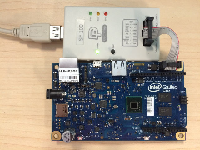 | |
| * Make sure ```dpcmd.exe``` is in ```PATH``` | |
| ```PATH=%PATH%;"c:\Program Files (x86)\DediProg\SF100"``` | |
| * **NOTE**: It is recommended that the FLASH image that was shipped with the | |
| Galileo development board be read and saved before updating FLASH image. The | |
| command shown below read the FLASH image and saves it to the file | |
| called ```GalileoOriginalFirmware.bin```. | |
| ```dpcmd.exe -r GalileoOriginalFirmware.bin``` | |
| * Update FLASH image using either the DediProg SF100 GUI or ```dpcmd.exe```. | |
| - Example update of Galileo firmware image when BUILDTARGET is DEBUG (default) | |
| ```dpcmd.exe -u%WORKSPACE%\Build\Quark\DEBUG_VS2015x86\FV\QUARK.fd ``` | |
| - Example update of Galileo firmware image when BUILDTARGET is RELEASE | |
| (```-b RELEASE```) | |
| ```dpcmd.exe -u%WORKSPACE%\Build\Quark\RELEASE_VS2015x86\FV\QUARK.fd ``` | |
| ## **Setting up a Serial Console and Booting to UEFI Shell** | |
| After the FLASH is updated on Galileo, a serial cable is connected between the | |
| host system and the Galileo target. A serial terminal emulator (such as | |
| [Tera Term](https://en.osdn.jp/projects/ttssh2/releases/)) can be used to see | |
| the logging messages from DEBUG() macros and the serial console for the UEFI | |
| Boot Manager, UEFI Shell, and operating system. | |
| The default serial communication parameters for the Intel(R) Galileo Gen 2 | |
| Development Board is 921600,n,8,1 with no hardware flow control. | |
| 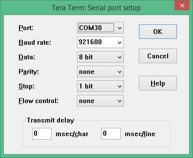 | |
| The default serial communication parameters for the Intel(R) Galileo Development | |
| Board is 461800,n,8,1 with no hardware flow control. | |
| The following changes to the [Tera Term](https://en.osdn.jp/projects/ttssh2/releases/) | |
| configuration files are recommended for UEFI serial console compatibility. | |
| Some of the later use cases involve using the TCPIP mode, so some of these | |
| recommendation apply to the TCPIP use cases. | |
| * TERATERM.INI - Set terminal size to 80 x 25 and terminal settings to UTF8. | |
| 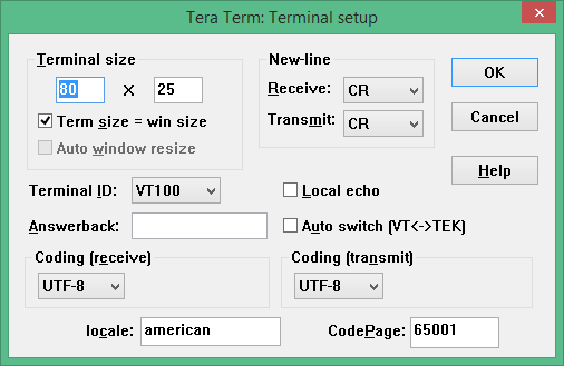 | |
| * TERATERM.INI - Set font type to Terminal to support box drawing glyphs. | |
|  | |
| * TERATERM.INI - Disable line mode to make TCPIP mode work like COM port mode. | |
| ```ini | |
| ; Line at a time mode | |
| EnableLineMode=off | |
| ``` | |
| * KEYBOARD.CNF - Disable VT function keys for F5..F10 | |
| ```ini | |
| [VT function keys] | |
| ;F6 key | |
| ;F6=64 | |
| ;F7 key | |
| ;F7=65 | |
| ;F8 key | |
| ;F8=66 | |
| ;F9 key | |
| ;F9=67 | |
| ;F10 key | |
| ;F10=68 | |
| ``` | |
| * KEYBOARD.CNF - Disable X function keys for F1..F4 | |
| ```ini | |
| [X function keys] | |
| ; F1 key | |
| XF1=off | |
| ; F2 key | |
| ;XF2=60 | |
| XF2=off | |
| ; F3 key | |
| ;XF3=61 | |
| XF3=off | |
| ; F4 key | |
| ;XF4=62 | |
| XF4=off | |
| ; F5 key | |
| ;XF5=63 | |
| ``` | |
| * KEYBOARD.CNF - Add UEFI serial console sequences for F1..F10 | |
| ```ini | |
| [User keys] | |
| User1=59,0,$1B[M | |
| User2=60,0,$1B[N | |
| User3=61,0,$1B[O | |
| User4=62,0,$1B[P | |
| User5=63,0,$1B[Q | |
| User6=64,0,$1B[R | |
| User7=65,0,$1B[S | |
| User8=66,0,$1B[T | |
| User9=67,0,$1B[U | |
| User10=68,0,$1B[V | |
| ``` | |
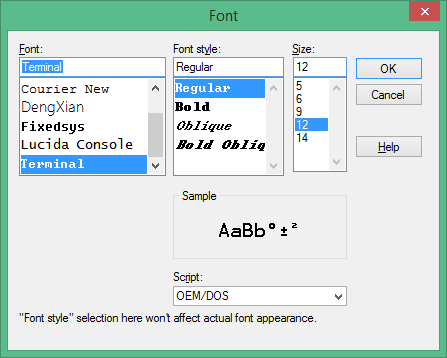
| Connect power adapter to Galileo development board, and the logging messages | |
| should be seen, followed by 5 second countdown, followed by an automatic boot to | |
| the built-in UEFI Shell. | |
|  | |
| ## **Source Level Debug Using Intel(R) UEFI Development Kit Debugger Tool** | |
| ### Pre-requisites | |
| * Intel(R) UEFI Development Kit Debugger Tool User Manual for Ver 1.5 or higher: | |
| Available from https://firmware.intel.com/develop/intel-uefi-tools-and-utilities/intel-uefi-development-kit-debugger-tool | |
| * Intel(R) UEFI Development Kit Debugger Tool Ver 1.5 or higher: Available from | |
| https://firmware.intel.com/develop/intel-uefi-tools-and-utilities/intel-uefi-development-kit-debugger-tool | |
| * [Tera Term](https://en.osdn.jp/projects/ttssh2/releases/) or other serial | |
| terminal emulator with TCPIP support | |
| Follow instructions in Intel(R) UEFI Development Kit Debugger Tool User manual | |
| to setup host system. | |
| Build a firmware image with SOURCE_DEBUG_ENABLE enabled | |
| (```-D SOURCE_DEBUG_ENABLE```). This will select the appropriate libraries, | |
| debug agent, and PCDs for Galileo. Galileo does not support a USB 2.0 debug | |
| port, so only the UART based communications library is used. | |
| Use Dediprog SF100 to update the Galileo development board FLASH image. | |
| Update the ```[Debug Port]``` section of the SoftDebugger.ini file with the host | |
| side UART configuration settings. The following example uses COM5, which must | |
| be updated with the COM port the Galileo target is attached. The following | |
| example also shows a baud rate of 921600 which is correct for a Galileo Gen 2. | |
| If a Galileo Gen 1 is being used, set the baud rate to 460800. By default, the | |
| Galileo console is redirected to TCPIP port 20715. | |
| ```ini | |
| [Debug Port] | |
| Channel = Serial | |
| Port = COM5 | |
| FlowControl = 0 | |
| BaudRate = 921600 | |
| Server = | |
| ``` | |
| Connect power adapter to Galileo development board and run a command script with | |
| the contents below to start a Tera Term session on TCPIP port 20715 and start | |
| the Intel(R) UEFI Development Kit Debugger Tool using UART connection between | |
| the host and target and WinDbg. The REBOOT button on the Galileo development | |
| board may need to be pressed for the debugger to perform the initial connect. | |
| ```cmd | |
| start "Console" /B "c:\Program Files (x86)\teraterm\ttermpro.exe" localhost:20715 /nossh | |
| start "Debugger" /B "C:\Program Files (x86)\Intel\Intel(R) UEFI Development Kit Debugger Tool\eXdi.exe" /LaunchWinDbg | |
| ``` | |
| The figure below should be seen when a connection is made. The SoftDebugger | |
| Debug Console window shows the status of the connection between the host and the | |
| target. The Tera Term window shows the console output from the SEC phase until | |
| the debug agent is initialized. The WinDbg window shows that the debugger is | |
| connected and the WinDbg application can be used for run control, breakpoint | |
| management, and viewing call stacks, local variables, global variables, etc. | |
|  | |
| ## **Debug Using Intel(R) System Debugger using OpenOCD** | |
| Setup hardware and software components following the instructions in the article at: | |
| https://software.intel.com/en-us/articles/using-intel-system-debugger-with-openocd | |
| Connect power adapter to Galileo development board. | |
| The following batch file starts Tera Term serial console on COM5 at 921600 baud, | |
| starts OpenOCD using a Flyswatter2, and starts Intel(R) System Studio Debugger. | |
| Select the **Connect** button to complete the host to target connection. | |
| ```cmd | |
| set OPENOCD="C:\Program Files (x86)\IntelSWTools\system_studio_for_windows_2016.0.023\debugger\openocd" | |
| start "Console" /B "c:\Program Files (x86)\teraterm\ttermpro.exe" /C=5 /BAUD=921600 | |
| start "OpenOcd" /B %OPENOCD%\bin\openocd.exe -f ..\scripts\interface\ftdi\flyswatter2.cfg -f ..\scripts\board\quark_x10xx_board.cfg | |
| call "C:\Program Files (x86)\IntelSWTools\System Debugger 2016\system_debugger\start_xdb_gdb_remote.bat" | |
| ``` | |
| When **Reset Target** is selected, the Galileo development board does not always | |
| halt at the first instruction at the reset vector. If debug is required from | |
| the first instruction of the reset vector, then update the file | |
| ```UefiCpuPkg/SecCore/Ia32/ResetVector.asm``` and change the two NOP | |
| instructions at the label ```ResetHandler:``` to ```JMP $```. This puts the CPU | |
| into a wait loop until the debugger is connected and the debugger is used to set | |
| instruction pointer to the next instruction. | |
| ``` | |
| ; | |
| ; For IA32, the reset vector must be at 0xFFFFFFF0, i.e., 4G-16 byte | |
| ; Execution starts here upon power-on/platform-reset. | |
| ; | |
| ResetHandler: | |
| ; nop | |
| ; nop | |
| jmp $ | |
| ApStartup: | |
| ; | |
| ; Jmp Rel16 instruction | |
| ; Use machine code directly in case of the assembler optimization | |
| ; SEC entry point relative address will be fixed up by some build tool. | |
| ; | |
| ; Typically, SEC entry point is the function _ModuleEntryPoint() defined in | |
| ; SecEntry.asm | |
| ; | |
| DB 0e9h | |
| DW -3 | |
| ``` | |
| ## **Install, Configure, and Boot Linux** | |
| * Download SD Card Linux Image: Available at | |
| http://www.intel.com/content/www/us/en/support/boards-and-kits/intel-galileo-boards/000005614.html | |
| * Extract the SD Card Linux Image to a FAT formatted Micro SD FLASH device | |
| * Install Micro SD FLASH device into Galileo development board | |
| Connect power adapter to Galileo development board and boot to the UEFI Shell. | |
| From the UEFI Shell execute the following commands to copy the GRUB EFI boot | |
| loader to ```\efi\boot\bootia32.efi```. This allows the UEFI Boot Manager, on | |
| all future boots, to auto detect that the Micro SD FLASH device is bootable. | |
| ``` | |
| Shell> connect -r | |
| Shell> map -r | |
| Shell> fs0: | |
| FS0:> mkdir efi | |
| FS0:> mkdir efi\boot | |
| FS0:> cp grub.efi efi\boot\bootia32.efi | |
| ``` | |
| The GRUB boot loader is set to a UART baud rate of 115200. A couple changes are | |
| required to change the baud rate to 460800 for Galileo Gen 1 or 921600 for | |
| Galileo Gen 2. From the UEFI Shell, execute the following commands to make a | |
| backup copy and edit the GRUB configuration file. | |
| ``` | |
| FS0:> cp boot\grub\grub.conf boot\grub\grub.conf.org | |
| FS0:> edit boot\grub\grub.conf | |
| ``` | |
| * Delete the lines associated with the boot option with the following title. | |
| ``` | |
| title Clanton SVP kernel-SPI initrd-SPI IMR-On IO-APIC/HPET NoEMU | |
| ``` | |
| * Replace the two instances of 115200 in the following line to 460800 for | |
| Galileo Gen 1 or 921600 for Galileo Gen 2. | |
| ``` | |
| kernel /bzImage root=/dev/ram0 console=ttyS1,115200n8 earlycon=uart8250,mmio32,$EARLY_CON_ADDR_REPLACE,115200n8 reboot=efi,warm apic=debug rw LABEL=boot debugshell=5 rootimage=image-full-galileo-clanton.ext3 | |
| ``` | |
| * Press F3 to save the file | |
| * Run the ```exit``` command to exit from the UEFI Shell and return to the | |
| UEFI Boot Manager | |
| * Select **Boot Manager** | |
| * Select **UEFI Misc Device** for the Micro SD FLASH device. | |
| * GRUB should run and Linux should boot with serial log messages. | |
| * When the serial log messages stop, change the Tera Term baud rate to 115200 | |
| * Login as ```root```. No password is required. | |
| * Use ```vi``` to edit ```/etc/inittab``` | |
| * Change the baud rate of ttyS1 from 115200 to 460800 for Galileo Gen 1 or | |
| 921600 for Galileo Gen 2. The line that need to be updated is shown below | |
| ``` | |
| S:2345:respawn:/sbin/getty 115200 ttyS1 | |
| ``` | |
| * Save the updated ```/etc/inittab``` | |
| * Run ```reboot -f``` to shutdown Linux and reboot the platform. | |
| * Set the Tera Term baud rate back to 460800 for Galileo Gen 1 or 921600 for | |
| Galileo Gen 2. | |
| After these changes both the EDK II firmware and the Linux operating system use | |
| the same baud rate. | |
| ### **Testing ACPI S3 Sleep** | |
| The ACPI S3 Sleep and Resume feature can be tested on a Galileo development | |
| board using the Real Time Clock (RTC) for a wake event. The shell script shown | |
| below arms the RTC wake alarm 10 seconds in the future and puts the system to | |
| sleep. A shorter time in seconds can be passed in as the first argument to the | |
| script, but do not use times shorter than 2 or 3 seconds. | |
| **NOTE**: The stmmac module is unloaded because the module is not compatible | |
| with S3 resume. | |
| ```sh | |
| # | |
| # Unload NIC driver that causes S3 to fail | |
| # | |
| rmmod stmmac | |
| # | |
| # Disable RTC wake alarm | |
| # | |
| echo 0 > /sys/class/rtc/rtc0/wakealarm | |
| # | |
| # Compute wake time that is $1 seconds in the future | |
| # | |
| let WakeTime=`date '+%s'` | |
| echo $WakeTime | |
| if ["$1" = ""]; then | |
| let WakeTime=$WakeTime+10 | |
| else | |
| let WakeTime=$WakeTime+$1 | |
| fi | |
| echo $WakeTime | |
| # | |
| # Enable RTC wake alarm $1 seconds in the future | |
| # | |
| echo $WakeTime > /sys/class/rtc/rtc0/wakealarm | |
| # | |
| # Put systems into ACPI S3 sleep state | |
| # | |
| echo mem > /sys/power/state | |
| ``` | |
| ## **UEFI Secure Boot Feature and Physical Presence** | |
| Build a firmware image with SECURE_BOOT_ENABLE enabled | |
| (```-D SECURE_BOOT_ENABLE```). This builds in support for UEFI authenticated | |
| variables, UEFI image verification, and UEFI Secure Boot configuration screens | |
| in the Device Manager. In order to change the UEFI Secure Boot configuration, | |
| the user must assert physical presence. The Galileo development board only has | |
| two push buttons (REBOOT and RESET). The REBOOT button unconditionally reboots | |
| the platform. The RESET button asserts the reset signal on the Arduino header | |
| and is also connected to a GPIO pin, so the state of the RESET button can be | |
| read. The user asserts physical presence by holding the RESET button while the | |
| Galileo development board boots, or by holding the RESET button while selecting | |
| the **Secure Boot Configuration** option in the Device Manager. | |
| Use Dediprog SF100 to update the Galileo development board FLASH image. | |
| Connect power adapter to Galileo development board and boot to the UEFI Boot | |
| Manager by pressing F2 or running the ```exit``` command from the UEFI Shell. | |
| Select **Device Manager** and then**Secure Boot Configuration**. Change | |
| **Customize Secure Boot** to **Customized** and then select **Custom Secure Boot | |
| Options**. If **Custom Secure Boot Options** can not be selected, then physical | |
| presence was not asserted using one of two methods listed above. Assert | |
| physical presence and try again. | |
| The **Custom Secure Boot Options** screen allows the Galileo development board | |
| to be enrolled into UEFI Secure Boot. See [How to Sign UEFI Drivers & Application V1.31]( | |
| http://sourceforge.net/projects/edk2/files/General%20Documentation/SigningUefiImages%20-v1dot31.pdf/download) | |
| in the [SecurityPkg Wiki](https://github.com/tianocore/tianocore.github.io/wiki/SecurityPkg) | |
| for details on how to complete the UEFI Secure Boot enrollment. | |
| ## **Enable Measured Boot Feature using Atmel I2C TPM on CryptoShield** | |
| Build a firmware image with MEASURED_BOOT_ENABLE enabled | |
| (```-D MEASURED_BOOT_ENABLE```) and TPM_12_HARDWARE set to ATMEL_I2C | |
| (```-D TMP_12_HARDWARE=ATMEL_I2C```). This builds in the TCG PEIM and DXE | |
| modules and uses the library for the Atmel I2C TPM hardware device. | |
| Use Dediprog SF100 to update the Galileo development board FLASH image. | |
| Attach the CryptoShield to the Arduino header of the Galileo development board | |
| as shown below. | |
|  | |
| Connect power adapter to Galileo development board and boot to the UEFI Shell. | |
| In the boot logging messages, messages similar to the following should be seen | |
| as the Atmel I2C TPM hardware device is detected and used to measure the | |
| contents of firmware volumes and firmware tables. | |
| ``` | |
| Loading PEIM at 0x0000FC75188 EntryPoint=0x0000FC75260 TrEEConfigPei.efi | |
| PROGRESS CODE: V03020002 I0 | |
| TrEEConfiguration.TpmDevice from Setup: 1 | |
| DetectTpmDevice: | |
| TpmDevice final: 1 | |
| TpmDevice PCD: 8B01E5B6-4F19-46E8-AB93-1C53671B90CC | |
| . . . | |
| Loading PEIM at 0x0000FC70190 EntryPoint=0x0000FC70260 TcgPei.efi | |
| PROGRESS CODE: V03020002 I0 | |
| Install PPI: E9DB0D58-D48D-47F6-9C6E-6F40E86C7B41 | |
| Install PPI: A030D115-54DD-447B-9064-F206883D7CCC | |
| PROGRESS CODE: V03020003 I0 | |
| The FV which is measured by TcgPei starts at: 0xFFF10000 | |
| The FV which is measured by TcgPei has the size: 0xF0000 | |
| The FV which is measured by TcgPei starts at: 0xFFD00000 | |
| The FV which is measured by TcgPei has the size: 0x1E0000 | |
| . . . | |
| Loading driver at 0x0000F620000 EntryPoint=0x0000F620260 TcgDxe.efi | |
| . . . | |
| TPM TcgDxe Measure Data when ReadyToBoot | |
| ``` | |
| See the [SecurityPkg Wiki](https://github.com/tianocore/tianocore.github.io/wiki/SecurityPkg) | |
| for additional details on EDK II TPM support | |
| ## **Measuring Boot Performance** | |
| Build a firmware image with PERFORMANCE_ENABLE enabled | |
| (```-D PERFORMANCE_ENABLE```). This builds in the UEFI Shell and the DP.EFI | |
| (Dump Performance) into a firmware volume and also includes a simple file system | |
| driver for firmware volumes so the DP.EFI command can be run out of the FLASH. | |
| Use Dediprog SF100 to update the Galileo development board FLASH image. | |
| Connect power adapter to Galileo development board and let it boot to the UEFI | |
| Shell. Then use the REBOOT button or the ```reset``` UEFI Shell command to | |
| reboot the Galileo development board. The first boot after a FLASH update does | |
| extra work that is only performed one time. In order to get correct performance | |
| measurements, use the 2nd or later boots. After the 2nd boot, run the | |
| ```dp -s``` command. The output should look similar to the figure below. | |
|  |